GeeKee CeeBee
Welcome to GeeKee CeeBee's Page: House of Mechatronics Projects & Lessons.
Contact Email: Ceebee1108@gmail.com
Follow me on Youtube
__________________________________________________________________________________________________________________________________
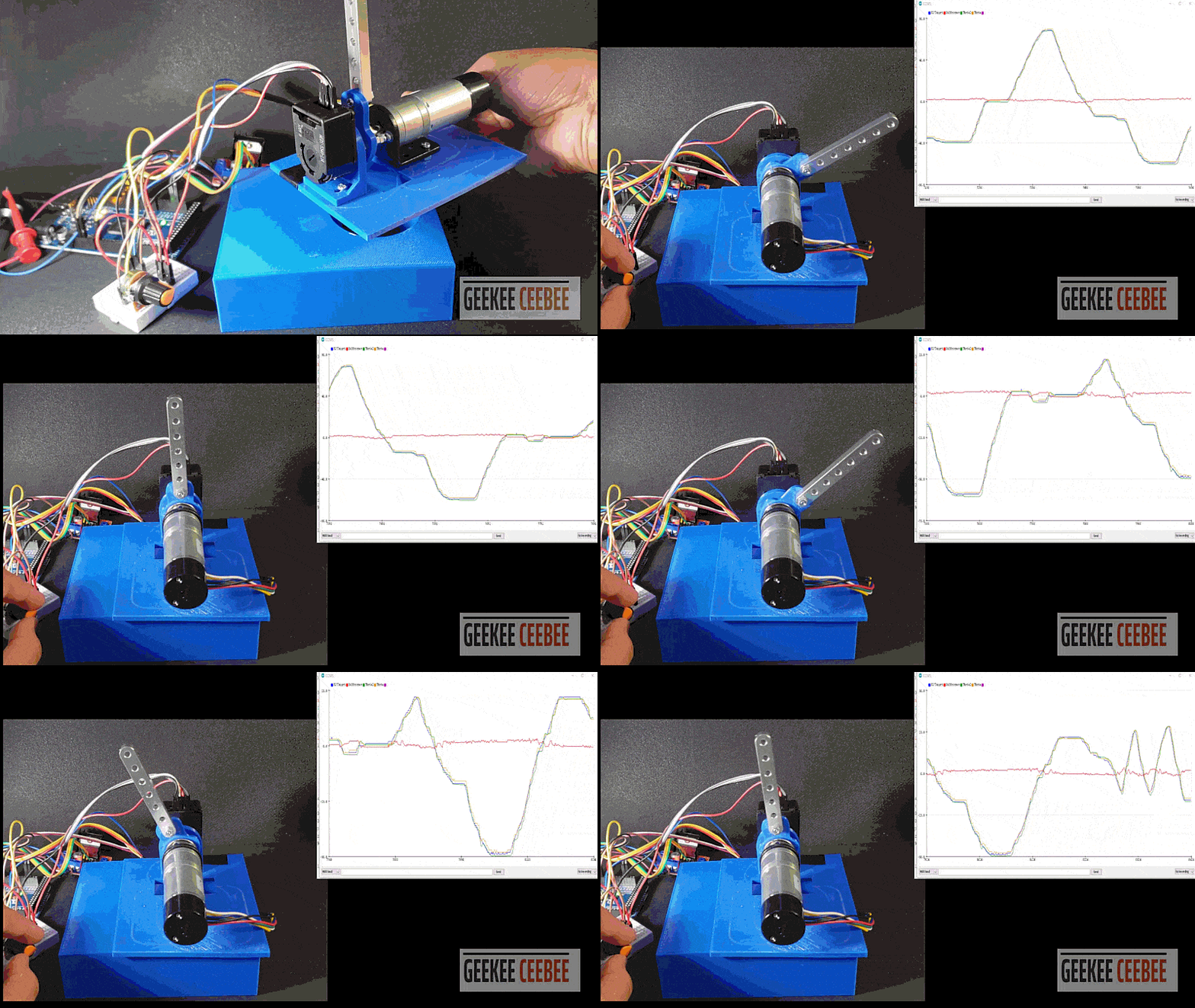
Anti-Backlash Dual Encoder Motor Position Control

Disclaimer: The code and other information on this project are provided on "AS IS" basis with no warranty. Please follow best practices and assess your own potential risks for this project.
Components List
Arduino Mega ( No Uno/Nano: Need 4 ISR pins) (Affiliate Link)
DC Motor with Optical Rotary Encoder (TS-25GA370)
500CPR HEDS Encoder
1X Rotary Potentiometer(Affiliate Link)
L298N Dual H-bridge Motor Driver (Affiliate Link)
DC Power Supply (6-12V) (Affiliate Link)
Jumper Wires and Breadboard (Affiliate Link)
Step-by-step video guide
Control Diagram

Wiring Diagram

__________________________________________________________________________________________________________________________________
Arduino Code
//GeeKee CeeBee


float kp = 1;
float ki = 0.0;
float kd = 40;
float Vmax = 10;
float Vmin = -10;
float V = 0.1;
long timer = 0;
unsigned long t;
unsigned long t_prev = 0;
int16_t e, e_prev,inte,inte_prev,error2, error2_prev, interror2;
const byte interruptPinA = 2;
const byte interruptPinB = 3;
const byte interruptPin2A = 18;
const byte interruptPin2B = 19;
volatile long EncoderCount = 0;
volatile long EncoderCount2 = 0;
float Theta, Theta2, RPM, RPM_d;
float MPU_angle;
int Theta_prev = 0;
int dt;
const byte PWMPin = 6;
const byte DirPin1 = 7;
const byte DirPin2 = 8;

void ISR_EncoderA() {
  bool PinB = digitalRead(interruptPinB);
  bool PinA = digitalRead(interruptPinA);

  if (PinB == LOW) {
    if (PinA == HIGH) {
      EncoderCount++;
    }
    else {
      EncoderCount--;
    }
  }

  else {
    if (PinA == HIGH) {
      EncoderCount--;
    }
    else {
      EncoderCount++;
    }
  }
}

void ISR_EncoderB() {

  bool PinB = digitalRead(interruptPinA);
  bool PinA = digitalRead(interruptPinB);

  if (PinA == LOW) {
    if (PinB == HIGH) {
      EncoderCount--;
    }
    else {
      EncoderCount++;
    }
  }

  else {
    if (PinB == HIGH) {
      EncoderCount++;
    }
    else {
      EncoderCount--;
    }
  }
}

void ISR_Encoder2A() {
  bool PinB = digitalRead(interruptPin2B);
  bool PinA = digitalRead(interruptPin2A);

  if (PinB == LOW) {
    if (PinA == HIGH) {
      EncoderCount2++;
    }
    else {
      EncoderCount2--;
    }
  }

  else {
    if (PinA == HIGH) {
      EncoderCount2--;
    }
    else {
      EncoderCount2++;
    }
  }
}


void ISR_Encoder2B() {

  bool PinB = digitalRead(interruptPin2A);
  bool PinA = digitalRead(interruptPin2B);

  if (PinA == LOW) {
    if (PinB == HIGH) {
      EncoderCount2--;
    }
    else {
      EncoderCount2++;
    }
  }

  else {
    if (PinB == HIGH) {
      EncoderCount2++;
    }
    else {
      EncoderCount2--;
    }
  }
}

void WriteDriverVoltage(float V, float Vmax) {
  int PWMval = int(255 * abs(V) / Vmax);
  if (PWMval > 255) {
    PWMval = 255;
  }
  if (V > 0) {
    digitalWrite(DirPin1, HIGH);
    digitalWrite(DirPin2, LOW);
  }
  else if (V < 0) {
    digitalWrite(DirPin1, LOW);
    digitalWrite(DirPin2, HIGH);
  }
  else {
    digitalWrite(DirPin1, LOW);
    digitalWrite(DirPin2, LOW);
  }
  analogWrite(PWMPin, PWMval);
}

void setup() {
  Serial.begin(9600);
  pinMode(interruptPinA, INPUT_PULLUP);
  pinMode(interruptPinB, INPUT_PULLUP);
  pinMode(interruptPin2A, INPUT_PULLUP);
  pinMode(interruptPin2B, INPUT_PULLUP);
  attachInterrupt(digitalPinToInterrupt(interruptPinA), ISR_EncoderA, CHANGE);
  attachInterrupt(digitalPinToInterrupt(interruptPinB), ISR_EncoderB, CHANGE);
  attachInterrupt(digitalPinToInterrupt(interruptPin2A), ISR_Encoder2A, CHANGE);
  attachInterrupt(digitalPinToInterrupt(interruptPin2B), ISR_Encoder2B, CHANGE);
  pinMode(DirPin1, OUTPUT);
  pinMode(DirPin2, OUTPUT);
  pinMode(A0, INPUT);
  Serial.println("Target, Difference, Theta2, Theta");
}

void loop() {
int target = map(analogRead(A0),0,1023,-90,90);
Theta2 = EncoderCount2/5.689;

for (int i=0; i<5; i++)  {
    t = millis();
    Theta = EncoderCount/6 ;
    dt = (t - t_prev);
    e = target - Theta;
    inte = inte_prev + (dt * (e + e_prev) / 2);
    V = kp * e + ki * inte + (kd * (e - e_prev) / dt) ; // Controlling Function
      if (V > Vmax) {
        V = Vmax;
        inte = inte_prev;
      }
      if (V < Vmin) {
        V = Vmin;
        inte = inte_prev;
        // val_prev= val;
      }
    WriteDriverVoltage(V, Vmax);
    Theta_prev = Theta;
    t_prev = t;
    inte_prev = inte;
    e_prev = e;
    delay(2);
}

error2 = target - Theta2;
V = 1.5 *error2;  ///using proportional controller with P-gain
WriteDriverVoltage(V, Vmax);

Serial.print(target);Serial.print(" ,");
Serial.print(Theta-Theta2);Serial.print(",");
 Serial.print(Theta2); Serial.print(" ,");
Serial.println(Theta);
delay(4);
}