GeeKee CeeBee

Welcome to GeeKee CeeBee's Page: House of Mechatronics Projects & Lessons.
Contact Email: Ceebee1108@gmail.com
Follow me on Youtube
__________________________________________________________________________________________________________________________________

Lane Keeping Assist System Using Steering Wheel

and CARLA Simulator

Demonstration video


__________________________________________________________________________________________________________________________________

Typical Lane Keeping Assist System

Lane-keeping assist system is responsible for detecting the lane departure and correcting the vehicle trajectory by adjusting the steering wheel by small angle in semi-autonomous vehicle. General elements and sub-modules of the LKAS are shown in Figure 1. Camera detects lane markings on the lane, State Observer calculates the vehicle dynamics which is used to calculate steering wheel angle and torque required. Further human-machine role negotiation algorithm is implemented to control the steering wheel of the vehicle. Apart from hardware issues, the challenge is to find the “correct code of communication” between human and machine [3].

__________________________________________________________________________________________________________________________________

CARLA Driving Simulator

CARLA simulator is an open-source driving simulator developed using C++ language and Unreal Game Engine vehicle physics. CARLA supports development, training and validation of autonomous urban driving systems that provides 3D photorealistic simulation as shown in Figure 5 [8]. CARLA allows a server-client interface that can be accessed using Python API as shown in Figure 6. CARLA world object allows easy access to built-in town maps with lane markings, road curbs, traffic lights, etc. and actors like vehicles and pedestrian. In addition, kinematic sensor for steering, braking and velocity measurements are also available including camera sensor for computer vision, plus the GPS location sensor [8]. In order to automatically extract markings in CARLA simulator, semantic segmentation camera sensor can be used. Lane lines can be highlighted using the detect_lanes function in CARLA as shown in Figure 7 [10].

__________________________________________________________________________________________________________________________________

MATLAB - Vehicle Lateral and Longitudinal Controller

Using kinematic vehicle dynamic equations and longitudinal vehicle forces equations, plant models are constructed in below Simulink model shown in Figure 10.

__________________________________________________________________________________________________________________________________

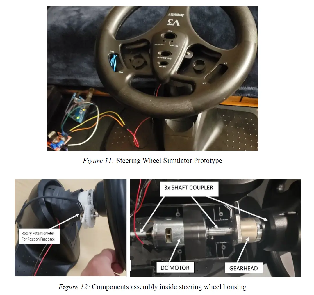
Steering Wheel Construction and CARLA Communication

In order to construct an ergonomic steering wheel simulator, an existing product, called Interact V3 Racing Wheel Controller, was repurposed. All the plastic housing and parts were salvaged from an old off-the-shelf gaming steering wheel controller. This plastic housing was fitted with rotary potentiometer for position sensing with the help of pair of gears, high rpm DC motor, and motor driver L298n and the planetary gear reduction (14:1) attachment to form a desired steering wheel simulator shown in Figure 11. Initial decision to use rotary quadrature encoder was scrapped due its compromised position accuracy. All components were mechanically attached to the plastic steering wheel as shown in Figure 12. Three shaft couplers were used to connect various components to each other.
In preparation to facilitate proper communication between steering wheel-pedals assembly and CARLA, the wiring and flow diagram shown in Figure 13 was developed and implemented. CARLA 0.95 Windows version and Python 3.7 were used in this study. Pedals assembly and Steering wheel assembly were connected to their individual Arduino microcontrollers. StandardFirmata code was uploaded to the Arduino interacting with pedals assembly. StandardFirmata is available in Arduino IDE under File > Examples > Firmata > StandardFirmata. Python PyFirmata [15] library was imported inside the main Python API code to form communication between pedals hardware and CARLA.
An example code file called manual_control.py available with CARLA [18] was modified to develop the main Python API code. Modifications include the means for receiving analog inputs from pedals hardware and interrupt signals from Steering wheel encoder. This API is responsible to communicate with the CARLA simulator world which consists of the all objects, blueprints, maps and actors. In other words, this API is simply an interface which defines communication between Steering wheel-pedals hardware and CARLA simulator. This API also contains the control algorithms used to implement vehicle longitudinal and lateral controller and also human machine controller.
Connect the Arduinos to the host PC via USB and determine their COM ports respectively. Assign COM ports in the main API code, respectively. To run the simulation, first run the CARLA server using “CarlaUE4.exe” file located in the CARLA folder. Note that Carla server will keep running in the background. To run the API open Command Prompt and jump to the folder directory where the API files is stored. And then type “py -3.7 –m API_file_name.py” and press Enter. A new window will open where the hardware get to interact in real time with CARLA world.


__________________________________________________________________________________________________________________________________

Controllers

Overall control algorithm layout is shown in Figure 14. Furthermore, waypoints depiction shown in Figure 15 were used to determine center of the lane at each time step of the simulation. Using the dot product and cross product of the car velocity vector and vector between the location of the car and location of the waypoint, the angle was determined. The goal of the lateral controller is to reduce this angle to zero. Longitudinal controller was to control the throttle and braking parameter of the vehicle as to maintain the set velocity of 11m/s. Since the potentiometer analog range was mapped to the 300 degrees rotational range. PD controller was used to implement tracking controller for the Steering wheel to track vehicle’s steering angle from the simulation.

__________________________________________________________________________________________________________________________________

RESULTS- Vehicle Longitudinal and Lateral Controller

Longitudinal controller results are shown in Figure 19 and 20. Actual drive cycle data (see Appendix B) was used for simulation of 150s. Controller tracks the drive cycle velocity very well. Moreover, the changes caused in the throttle/ braking force of the vehicle due to the changes in its velocity seem realistic. As the velocity of the vehicle decreases the propulsion forces also decreases, and vice versa. In addition, these results align with results presented by Kumbhani et al. [7].
Moreover, lateral controller results are shown in Figure 21 and 22. To demonstrate the controller’s effectiveness during vehicle’s lateral position tracking, multistep velocity input was used in the simulation of 60s. During lane change small changes in vehicle’s lateral position is expected. Thus, the controller is tested at 5m change in lateral position while driving at various speed. Controller behaves quite well while tracking the lateral position. Plus, changes in vehicle’s steering angle validates vehicle realistic behavior. Once again, these results align with the results presented by Kumbhani et al. [7].

__________________________________________________________________________________________________________________________________

RESULTS- Steering Wheel and Pedals Testing with CARLA

Communication of steering wheel and pedals hardware with CARLA simulator was successfully achieved. Complete steering wheel setup while in use is shown in Figure 23. Turning the steering wheel caused the vehicle to turn as intended in the simulation. Throttle and brake pedals also performed as intended. The content of the example code allowed an overlay over the simulation screen which displays status bars for steering angle, acceleration and braking measurements. Synchronize mode was enabled to perform event synchronization between python API and the server simulation. Overall open loop control worked as intended.
Control algorithms implementation was also tested. Test setup is shown in Figure 24. Results can be seen in Figures 25-28. Longitudinal controller was used to maintain the vehicle velocity at 11m/s. Lateral controller was used to keep the vehicle within the lane, more precisely on the center of the lane. Human input was added to rotate the steering wheel and with the help of switching algorithm vehicle control was handed over to the operator while automatic controller renders ineffective. Overall, control algorithm successfully recognized the human operator as superior controller by determining the amount of counter torque applied to the steering wheel by the human operator.

__________________________________________________________________________________________________________________________________

CONCLUSION - Summary and Future Work

Vehicle lateral and longitudinal control model was constructed and validated using published results. Preliminary DC motor model was developed, but not validated. An ergonomic steering wheel and pedal system was assembled to control vehicle steering angle, acceleration and braking. Handshake was formed between steering-pedals hardware with CARLA simulator on host PC with Arduino microcontroller. Successful open loop and closed loop testing was performed by controlling the vehicle in CARLA. Low level human machine interaction control algorithm was successfully implemented between steering wheel hardware and the CARLA driving simulation. Overall, the huge portion of the project goal was accomplished.
Additional work is to be done to validate the DC motor model. Refine and improve the steering-pedal hardware performance interacting with CARLA simulator. Further analyze and study the human-machine interaction in LKAS using the developed stationary steering simulator. Implement perception aspect of the controls to recognize road curvature and adjust the velocity profile accordingly. Overall, existing code and control algorithm can be further refined and optimized for the better results.

__________________________________________________________________________________________________________________________________

REFERENCES

[1] National Highway Traffic Safety Administration “Drowsy Driving.” NHTSA, 22 July 2019, www.nhtsa.gov/risky-driving/drowsy-driving.
[2] Kala, Rahul. “Advanced Driver Assistance Systems.” On-Road Intelligent Vehicles, 2016, pp. 59–82., doi:10.1016/b978-0-12-803729-4.00004-0.
[3] Pohl, Jochen, and Jonas Ekmark. “A LANE KEEPING ASSIST SYSTEM FOR PASSENGER CARS-DESIGN ASPECTS OF THE USER INTERFACE.” Www.semanticscholar.org, Volvo Car Corporation, 2003, pdfs.semanticscholar.org/f3a5/5945bb5738a463dc2a1bb10c6bdecb863b1b.pdf.
[4] Kong, Jason, et al. “Kinematic and Dynamic Vehicle Models for Autonomous Driving Control Design.” 2015 IEEE Intelligent Vehicles Symposium (IV), 2015, doi:10.1109/ivs.2015.7225830.
[5] Rajamani, Rajesh. Vehicle Dynamics and Control. 2nd ed. Chp. 2, Springer US, 2012.
[6] R. Attia, R. Orjuela, and M. Basset, “Longitudinal Control for Automated Vehicle Guidance,” IFAC Proceedings, Vol. 45, pp. 65–71, 2012.
[7] Kumbhani, Nikunj, and Saeid Bashash. “A Supervisory Lateral Slip Prevention Controller for Autonomous Vehicles.” Volume 2: Modeling and Control of Engine and After treatment Systems, 8 Oct. 2019, doi:10.1115/dscc2019-9166.
[8] Dosovitskiy, Alexey et al. “CARLA: An Open Urban Driving Simulator.” CoRL (2017). www.researchgate.net/publication/321025516_CARLA_An_Open_Urban_Driving_Simulator.
[9] CARLA team. CARLA Documentation. 2020. url: https://carla.readthedocs.io/en/latest/.
[10] Cattaruzza, Marco. “Design and Simulation of Autonomous Driving Algorithms.” Semanticscholar.org, POLITECNICO DI TORINO, 26 July 2019, pdfs.semanticscholar.org/da4a/2068af00af0a57abad98e9dd98375b75b9ed.pdf.
[11] Brogle, C., & Braunl, T. (2018, October 22). Software Architecture and Hardware-in-the-loop Simulation for an Autnoumous Formula SAE Vehicle [Scholarly project]. In Https://robotics.ee.uwa.edu.au. Retrieved March, 2020, from https://robotics.ee.uwa.edu.au/theses/2018-REV-HardwareInTheLoopSimulation-Brogle.pdf
[12] Quigley, M., Gerkey, B., Conley, K., Faust, J., Foote, T., Leibs, J., . . . Ng, A. (2009). ROS: An open-source Robot Operating System. IEEE International Conference on Robotics and Automation.https://pdfs.semanticscholar.org/d45e/aee8b2e047306329e5dbfc954e6dd318ca1e. pdf?_ga=2.144489781.1612373857.1590370161-2052722152.1579675840
[13] https://github.com/firmata/protocol
[14] Huang, Y., Yu, F., & Li, D. (2017). The Inversion of C/S Based on Protocol Firmata. Proceedings of the 2017 International Conference on Electronic Industry and Automation (EIA 2017). doi:10.2991/eia-17.2017.2
[15] https://pypi.org/project/pyFirmata/
[16] https://github.com/MrYsLab/pymata-aio/wiki/Uploading-FirmataPlus-to-Arduino
[17] https://github.com/MrYsLab/pymata-aio/wiki
[18] https://carla.org/2019/04/03/release-0.9.5/
[19] Time Wescott, “Applied Control Theory for Embedded Systems”, ISBN-13: 978-0750678391, 2006, https://www.wescottdesign.com/articles/Friction/friction.pdf

__________________________________________________________________________________________________________________________________